 ▼
▼
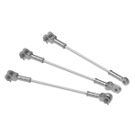
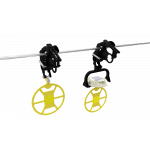
Distribution Tie

Distribution Ties provide a vastly improved method of securing the conductor in the top groove of interchangeable headstyle insulators compared to hand ties. These performance ties provide superior abrasion protection for the conductor under all types of motion, including low-frequency sway oscillation, high-frequency aeolian vibration, and galloping. The included tie tube provides an armoring layer that eliminates abrasion damage of the conductor and insulator caused by conductor motion, extending the life of the electrical system and reducing maintenance. gh.
-
Applicable to all interchangeable headstyle insulators
-
Accommodates conductors from 0.190" - 1.585"
-
Pre-contoured design ensures a tight and secure fit
-
Mitigates long-term issues caused by Radio Influence Voltage (RIV)
-
Accommodates line angles up to 10-degrees in the vertical orientation
-
Exceeds NESC requirements for unbalanced load
-
Reduces abrasion caused by vibration
-
Ideal solution for system hardening and severe weather applications
-
Resiliency of the tie protects the conductor
-
Test reports available upon request
Product Information
Distribution Tie - Insulator Ties Catalog Pages
Insulator/Tie Fit Information Sheet
Severe Weather Tie Kits - Sell Sheet
Installation Instructions
|
Diameter Range |
Nominal Conductor Size1 | Units per Carton | C-Neck Insulators (Black) | F-Neck Insulators (Yellow) | Conductor Color Code | |||||
| in | Catalog Number | Applied Length | Catalog Number | Applied Length | ||||||
| Minimum | Maximum | in | in | |||||||
| 0.190 | 0.215 |
#6, 6/1; #4, 7W Comp. |
100 | UTC-1100 | 24 | UTF-1200 | 25 | Blue | ||
| 0.216 | 0.244 |
#4, 7W All Alum.; #4, 6/1, 7/1 Comp. |
100 | UTC-1101 | 25 | UTF-1201 | 26 | Brown | ||
| 0.245 | 0.277 |
#4, 6/1, 7/1; #4, 7W Alum. Alloy |
100 | UTC-1102 | 26 | UTF-1202 | 27 | Orange | ||
| 0.278 |
0.315 |
#3, 7W Alum. Alloy; #2, 7W All eAlum. |
100 | UTC-1103 | 26 | UTF-1203 | 29 | Purple | ||
| 0.316 | 0.357 |
#2, 6/1, 7/1; #2, 7W Alum. Alloy; #1, 6/1 ACSR |
100 | UTC-1104 | 28 | UTF-1204 | 31 | Red | ||
| 0.358 | 0.405 |
1/0, 7W All Alum.; 1/0, 6/1 ACSR; 1/0, 7W Alum. Alloy |
100 | UTC-1105 | 30 | UTF-1205 | 32 | Yellow | ||
| 0.406 | 0.459 |
2/0, 7W All Alum.; 2/0, 6/1 ACSR; 2/0, 7W Alum. Alloy |
50 | UTC-1106 | 25 | UTF-1206 | 26 | Blue | ||
| 0.460 | 0.520 |
3/0, 7W All Alum.; 3/0, 6/1 ACSR; 3/0, 7W Alum. Alloy |
50 | UTC-1107 | 25 | UTF-1207 | 27 | Orange | ||
| 0.521 | 0.588 |
4/0, 7W All Alum.; 4/0, 6/1 ACSR; 4/0, 7W Alum. Alloy |
50 | UTC-1108 | 28 | UTF-1208 | 29 | Red | ||
| 0.589 | 0.665 |
266.8, 37W All Alum.; 266.8, 18/1 |
50 | UTC-1109 | 30 | UTF-1209 | 32 | Purple | ||
| 0.666 | 0.755 |
336.4, 19W All Alum.; 336.4, 18/1; 397.5, 19W All Alum. |
50 | UTC-1110 | 31 | UTF-1210 | 32 | Brown | ||
| 0.756 | 0.858 |
477, 19W, 37W All Alum.; 477, 18/1 24/7, 26/7 |
50 | UTC-1111 | 32 | UTF-1211 | 33 | Red | ||
| 5/8" R. Groove2 | ||||||||||
| 0.859 | 0.968 |
556.5, 26/7; 636, 18/1; 700, 37W, 61W All Alum. |
50 | UTC-1112 | 34 | UTF-1212 | 35 | Blue | ||
| 3/4" R. Groove2 | ||||||||||
| 0.969 | 1.096 |
795, 37W All Alum.; 795, 61W All Alum.; 715.5, 24/7; 795, 54/7 |
50 | UTC-1113 | 37 | UTF-1213 | 39 | Green | ||
| 1.097 | 1.240 |
954, 36/1, 54/7; 1033.5, 37W, 61W All Alum. |
50 | UTC-1114 | 40 | UTF-1214 | 41 | Yellow | ||
|
1" R. Groove2 |
||||||||||
| 1.241 | 1.402 |
1033.5, 54/7; 1272, 45/7 |
50 | UTF-1215 | 43 | Orange | ||||
| 1.403 | 1.585 |
1351.5, 54/19; 1590, 45/7 |
50 | UTF-1216 | 45 | Black | ||||
|
Right-hand lay standard NOTES: 1 Nominal Conductor Size indicates one or more of various conductors within each range. 2 For the succeeding ranges the insulator's side groove radius should be at least as large as shown above. |
||||||||||