 ▼
▼
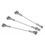
Distribution Tie


Distribution Ties manufactured of aluminum covered steel secure conductors in the top groove of interchangeable headstyle insulators. They can accommodate conductor diameters from .190" to 1.585" for F neck insulators and .190" to 1.240" for other size insulators as long as the insulator top groove is large enough.
- Provide an improved method of securing conductor compared to clamp-top insulators or hand ties over Armor Rods
- Provides superior abrasion protection for the conductor under all types of motion
- The tube component surrounds the bare conductor with a resilient cushion
- Plast Line Ties are also offered as an alternate to metal ties applied over plastic jacketed conductor
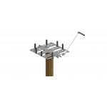
Application Procedures
Catalog Pages
Distribution Tie - Insulator Ties Catalog Pages
Insulator/Tie Fit Information Sheet
Sales Material
|
Diameter Range |
Nominal Conductor Size1 | Units per Carton | C-Neck Insulators (Black) | F-Neck Insulators (Yellow) | Conductor Color Code | |||||
| in | Catalog Number | Applied Length | Catalog Number | Applied Length | ||||||
| Minimum | Maximum | in | in | |||||||
| 0.190 | 0.215 |
#6, 6/1; #4, 7W Comp. |
100 | UTC-1100 | 24 | UTF-1200 | 25 | Blue | ||
| 0.216 | 0.244 |
#4, 7W All Alum.; #4, 6/1, 7/1 Comp. |
100 | UTC-1101 | 25 | UTF-1201 | 26 | Brown | ||
| 0.245 | 0.277 |
#4, 6/1, 7/1; #4, 7W Alum. Alloy |
100 | UTC-1102 | 26 | UTF-1202 | 27 | Orange | ||
| 0.278 |
0.315 |
#3, 7W Alum. Alloy; #2, 7W All eAlum. |
100 | UTC-1103 | 26 | UTF-1203 | 29 | Purple | ||
| 0.316 | 0.357 |
#2, 6/1, 7/1; #2, 7W Alum. Alloy; #1, 6/1 ACSR |
100 | UTC-1104 | 28 | UTF-1204 | 31 | Red | ||
| 0.358 | 0.405 |
1/0, 7W All Alum.; 1/0, 6/1 ACSR; 1/0, 7W Alum. Alloy |
100 | UTC-1105 | 30 | UTF-1205 | 32 | Yellow | ||
| 0.406 | 0.459 |
2/0, 7W All Alum.; 2/0, 6/1 ACSR; 2/0, 7W Alum. Alloy |
50 | UTC-1106 | 25 | UTF-1206 | 26 | Blue | ||
| 0.460 | 0.520 |
3/0, 7W All Alum.; 3/0, 6/1 ACSR; 3/0, 7W Alum. Alloy |
50 | UTC-1107 | 25 | UTF-1207 | 27 | Orange | ||
| 0.521 | 0.588 |
4/0, 7W All Alum.; 4/0, 6/1 ACSR; 4/0, 7W Alum. Alloy |
50 | UTC-1108 | 28 | UTF-1208 | 29 | Red | ||
| 0.589 | 0.665 |
266.8, 37W All Alum.; 266.8, 18/1 |
50 | UTC-1109 | 30 | UTF-1209 | 32 | Purple | ||
| 0.666 | 0.755 |
336.4, 19W All Alum.; 336.4, 18/1; 397.5, 19W All Alum. |
50 | UTC-1110 | 31 | UTF-1210 | 32 | Brown | ||
| 0.756 | 0.858 |
477, 19W, 37W All Alum.; 477, 18/1 24/7, 26/7 |
50 | UTC-1111 | 32 | UTF-1211 | 33 | Red | ||
| 5/8" R. Groove2 | ||||||||||
| 0.859 | 0.968 |
556.5, 26/7; 636, 18/1; 700, 37W, 61W All Alum. |
50 | UTC-1112 | 34 | UTF-1212 | 35 | Blue | ||
| 3/4" R. Groove2 | ||||||||||
| 0.969 | 1.096 |
795, 37W All Alum.; 795, 61W All Alum.; 715.5, 24/7; 795, 54/7 |
50 | UTC-1113 | 37 | UTF-1213 | 39 | Green | ||
| 1.097 | 1.240 |
954, 36/1, 54/7; 1033.5, 37W, 61W All Alum. |
50 | UTC-1114 | 40 | UTF-1214 | 41 | Yellow | ||
|
1" R. Groove2 |
||||||||||
| 1.241 | 1.402 |
1033.5, 54/7; 1272, 45/7 |
50 | UTF-1215 | 43 | Orange | ||||
| 1.403 | 1.585 |
1351.5, 54/19; 1590, 45/7 |
50 | UTF-1216 | 45 | Black | ||||
|
Right-hand lay standard NOTES: 1 Nominal Conductor Size indicates one or more of various conductors within each range. 2 For the succeeding ranges the insulator's side groove radius should be at least as large as shown above. |
||||||||||